The execution of a successful styling program requires seamless collaboration of multiple departments. Industrial design, marketing, engineering, manufacturing and executive leadership each bring unique perspectives and expertise to the table. This blog explores how these disciplines can work together to achieve a cohesive and impactful styling program.
Industrial Design
Industrial design is primarily concerned with the aesthetics, functionality, and ergonomics of a product. Designers focus on creating visually appealing and user-friendly products that meet the needs of consumers. In a styling program, industrial designers play a crucial role in conceptualizing and developing designs that reflect the brand’s identity and resonate with the target audience. They monitor industry trends and draw inspiration from other sectors to create modern, innovative designs.
Key Contributions
Concept development: Industrial designers generate innovative ideas and sketches for product designs.
Prototype creation: Designers build prototypes to test and refine design concepts.
Material selection: Choosing appropriate materials to enhance product aesthetics and functionality. Often considering manufacturing methods and build quality for product volumes.
Marketing
Marketing is essential for understanding consumer preferences, market trends, and competitive landscapes. Marketers translate the design vision into a compelling story that attracts and engages customers. They also ensure that the styling program aligns with the overall brand strategy and drives sales.
Key Contributions
Market research: Conducting research to identify consumer needs and preferences.
Brand positioning: Developing strategies to position the product effectively in the market.
Promotional campaigns: Crafting compelling marketing campaigns to promote the product.
Engineering
Engineering is responsible for turning design concepts into feasible products. Engineers ensure that the designs meet technical specifications, are manufacturable, and comply with safety standards. Their expertise is vital in solving complex technical challenges and optimizing product performance.
Key Contributions
Technical feasibility: Assessing whether design concepts can be realistically produced.
Product development: Creating detailed product specifications and blueprints.
Quality assurance: Ensuring products meet quality and safety standards.
Executive Leadership
Executive leadership provides strategic direction and resources needed for the successful execution of a styling program. Leaders ensure that the program aligns with the company’s vision and goals, and they make sure the design language is consistent with other product lines within the larger organisation.
Key Contributions
Vision setting: Defining the strategic objectives and desired outcomes of the styling program. Define product features that make sense for that specific market segment.
Resource allocation: Providing necessary resources and support to execute the program.
Decision-making: Making critical decisions to steer the program towards success.
Key Enablers
Establish customer focus groups for styling, where industrial designers listen to customer feedback. Ensure designers sketch rapidly to accurately capture customers’ preferences, acknowledging that styling is subjective.
Regularly communicate with all stakeholders to ensure the design language is maintained throughout the detailed design and manufacturing processes.
Involve the Industrial Design team from the early stages of product development and consult with them throughout to ensure their vision is maintained.
Revisit customers during advanced product development to confirm the design meets expectations.
Conclusion
The collaboration between industrial design, marketing, engineering, and executive leadership is essential for the successful execution of a styling program. Each discipline contributes unique insights and expertise, fostering innovation and ensuring that the final product resonates with consumers and achieves commercial success. By working together, these departments can create products that are not only visually appealing but also functional, marketable, and aligned with the company’s strategic goals.
In product development, the choice of manufacturing process is rarely questioned once initial designs are established. However, some of the most significant cost and performance breakthroughs come from challenging these fundamental assumptions. This case study explores how cross-industry manufacturing expertise transformed an RV front cap design, delivering exceptional results through strategic process innovation and supplier collaboration.
The project demonstrates key principles in Design for Manufacturing (DFM), strategic decision-making, and the value of cross-industry knowledge transfer in solving complex engineering challenges.
The Challenge
Original Design Constraints
The front cap design for a major RV manufacturer utilized bent metal round tubes through a hydroforming process. While functional, this approach presented several limitations:
Manufacturing complexity: Expensive hydroforming tooling with multiple forming operations
Assembly challenges: Multiple tube welding and fastening steps increased production time
Cost pressures: High tooling investment with limited design flexibility
Business Requirements
The project faced aggressive targets:
Significant cost reduction across tooling and production
Increased usable interior volume without weight penalty
Improved manufacturing scalability
Accelerated time-to-market
The Breakthrough: Process Innovation
Cross-Industry Insight
The solution came from applying agricultural equipment manufacturing knowledge to the RV industry. Years of designing structural styling panels for combines and harvesters revealed that thermoforming could serve structural purposes beyond aesthetic applications—a possibility the RV industry had overlooked.
Process Transformation Analysis
Factor
Original: Hydroformed Tubes
Solution: Thermoformed Structures
Tooling Cost
$$$$
$$
Design Flexibility
Limited by bending
High (3D freedom)
Assembly
Multiple operations
Simplified bonding
Lead Time
12-16 weeks
6-8 weeks
Volume Optimization
Constrained
Geometry-optimized
Why Thermoforming Worked
Structural Efficiency: Optimized profiles provide excellent stiffness while enabling complex 3D geometries tailored for specific load cases (wind, vibration, snow).
Transparency enables solutions: Honest identification of challenges opens problem-solving opportunities
Engineering support creates success: Technical collaboration helps suppliers overcome obstacles
Cost visibility matters: Understanding total program economics drives better decisions
Lessons Learned
Challenge Assumptions Early
The hydroformed tube approach seemed established and unchangeable. Early intervention with alternative process evaluation saved significant investment and enabled performance improvements.
Takeaway: Manufacturing process should be evaluated, not assumed.
Cross-Industry Experience Drives Innovation
Agricultural equipment knowledge revealed structural thermoforming possibilities that RV industry specialists had overlooked. Diverse industry experience identifies unconventional solutions.
Takeaway: Look beyond industry boundaries for proven solutions to similar challenges.
Collaborative Problem-Solving Creates Value
Working closely with suppliers to address manufacturing challenges transformed obstacles into competitive advantages and strengthened partnerships.
Takeaway: Engineering support enables supplier success and builds long-term relationships.
Total System Optimization
Success came from optimizing across multiple dimensions simultaneously: performance (volume increase), cost (tooling and piece price reduction), manufacturing (assembly simplification), and flexibility (design iteration capability).
Takeaway: Evaluate total program economics, not individual component costs.
Validate Through Prototyping
Thorough prototyping and testing validated both the structural approach and manufacturing feasibility, reducing production risk.
Takeaway: Invest in validation to derisk innovative approaches.
Conclusion
This case study demonstrates how strategic process evaluation and supplier collaboration deliver breakthrough results. By challenging accepted manufacturing methods, applying cross-industry knowledge, and engaging suppliers collaboratively, the project achieved seemingly contradictory goals: increased performance, reduced cost, and accelerated timeline.
The lessons extend beyond this specific application. Whether in RV, agricultural equipment, consumer products, or industrial applications, the principles remain constant:
Question process assumptions based on deep manufacturing knowledge
Apply proven solutions from related industries
Engage suppliers as problem-solving partners
Transfer knowledge across industry boundaries
Optimize total system economics, not individual components
Manufacturing innovation often comes not from accepting constraints as given, but from asking whether better approaches exist. With the right expertise and collaborative mindset, transformative improvements are achievable.
The key is recognizing that the most elegant solution to a design challenge may not be optimizing the current process—it may be questioning whether you’re using the right process at all.
About This Case Study
This project demonstrates the manufacturing-first design thinking and cross-industry expertise that VEDA brings to client engagements. Based on work during our founder’s product development consulting career, it exemplifies how deep manufacturing knowledge combined with strategic supplier engagement can unlock breakthrough results.
Class ‘A’ surfacing is a critical aspect of design and manufacturing, particularly in the automotive and aerospace industries. The principles are applicable for other industries such as Agricultural, Mining and Electronics. This blog delves into the intricacies of Class ‘A’ surfacing, providing a thorough understanding of its principles, techniques, and applications.
Introduction to Class ‘A’ Surfacing
Class ‘A’ surfacing means making top-notch, visually stunning surfaces that look great and meet precise design and engineering criteria. These surfaces are usually found in the most noticeable parts of a product, where they really need to shine.
Class A surface is anything that you the customer sees. i.e. exterior panels and interior surfaces.
Class B surface is something that is not always visible i.e. the underside of a fascia that you would have to bend down to see.
Class C surface is the back side of a part of a surface that is permanently covered by another part.
Analyzing A Class Surface
Analysis of Class ‘A’ surfaces, highlighting the importance of smoothness, continuity, and curvature. Zebra plots, reflection analysis are tools that can be used to detect if there is a deviation in flow of the surfaces. Creating curves at intervals and analysing curvature plots and how the length of the band is getting affected by the change in geometry is a good way to pick out problem areas and course correct them. Reading curvature plots and zebra curves can be tricky and takes years of experience to master.
Bezier Curves and Surface Modeling
One of the key techniques is the use of Bezier curves in surface modeling. Bezier curves are mathematical representations that allow designers to create complex, smooth curves with a high degree of control. The presentation explains how these curves are used to define the shape and flow of Class ‘A’ surfaces.
Modeling practices
If you take two adjoining 2D lines, or a couple of tangential surfaces, the intersection between them can be turned into an arc (2D) or a fillet (3D), each of which is inserted with a constant radius. However the transition from each line or surface can often be too abrupt for the design.
Fillets should look simple – you shouldn’t see a fillet line in a model. They should also be simple to create. “Achieving tangent and curvature continuity in complex shapes on other systems is hard work.
A reduction in the weight of a curve will allow it to retain its tangency, but sharpen the change in curvature. This can be seen most effectively by reducing the weight almost to zero.
History of Surface Modeling
Surface modeling was developed in the automotive and aerospace industries in the late 1970s to design and manufacture complex shapes. Nurbs — nonuniform rational B-splines and cubic-surface formats appeared early and remain the primary spline and surface formats used throughout the CAD industry, tracing its evolution from early manual techniques to modern computer-aided design (CAD) tools.
Types of Continuity
Understanding the different types of continuity is crucial for Class ‘A’ surfacing.
Point Continuity (also known as G0 continuity) – will produce a reflection on one surface, then at the boundary disappear and re-appear at a location slightly different on the other surface. The same reflective phenomenon will show when there is a gap between the surfaces.
Tangent Continuity (also known as G1 continuity) – will produce a reflection on one surface, then at the boundary have a kink and continue. Unlike Point continuity the reflection (repeat REFLECTION) is continuous but has a tangent discontinuity in it.
Curvature Continuity (also known as G2 continuity – this will produce unbroken and smooth reflection across the boundary.
Higher order continuity, (G3 continuity) represents an even higher level of smoothness and continuity between surfaces. It requires not only tangent and curvature continuity but also ensures a continuous change in the rate of curvature throughout the transition. To achieve G3 continuity, the curvature combs should be heading in the same direction, be the same length, and also be tangent
Capabilities
Ultimately, a good CAD system shields users from having to know too much about the mathematics that represent the underlying surfaces. In addition, surface modelers should provide enough tools to completely define any feature on the part using surfaces.
Have many functions for defining the different shapes of surfaces including ruled, revolved, lofted, extruded, swept, offset, filleted, blended, planar boundary, and drafted. Each of these functions have further variations. There are surfacing software like Alias, Catia, ICEM Surf that can handle faster iterations and used to create Class A surfaces. It is tough to create a good curvature continuous surface in Creo, UG, Solidworks but not impossible. Going through concept phases is time consuming as the surfacing capabilities of these software is limited. Ultimately surfaces created in Software such as Alias will be translated into something like Creo for engineering design and manufacturing.
Conclusion
Class ‘A’ surfacing is a sophisticated and vital aspect of modern design and manufacturing. By understanding and mastering Class ‘A’ surfacing, designers and engineers can achieve the perfect balance of form and function, creating products that are not only visually stunning but also meet the highest standards of performance and quality.
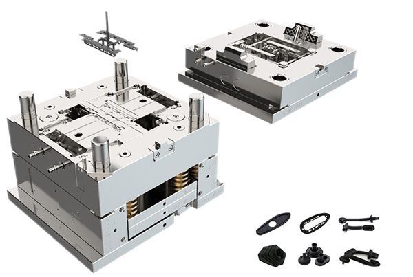
In the world of Product Development especially in products that rely on plastic parts, mold design knowledge holds immense significance. More often this knowledge could define product functionality and foster innovation. Choosing the right process and material at the start of the design phase is key to product quality, cost-effectiveness and reliability of the final product. Having knowledge of Mold development cycles and key manufacturing methodologies involved in Mold Manufacturing can aid in cutting down rework costs and timelines significantly. This document delves into the various dimensions of mold design and underscores its significance in the realm of plastic part design. The focus will be on Injection Mold Design however these principles can be translated to other processes such ad Blow, Compression, Thermoforming to name a few.
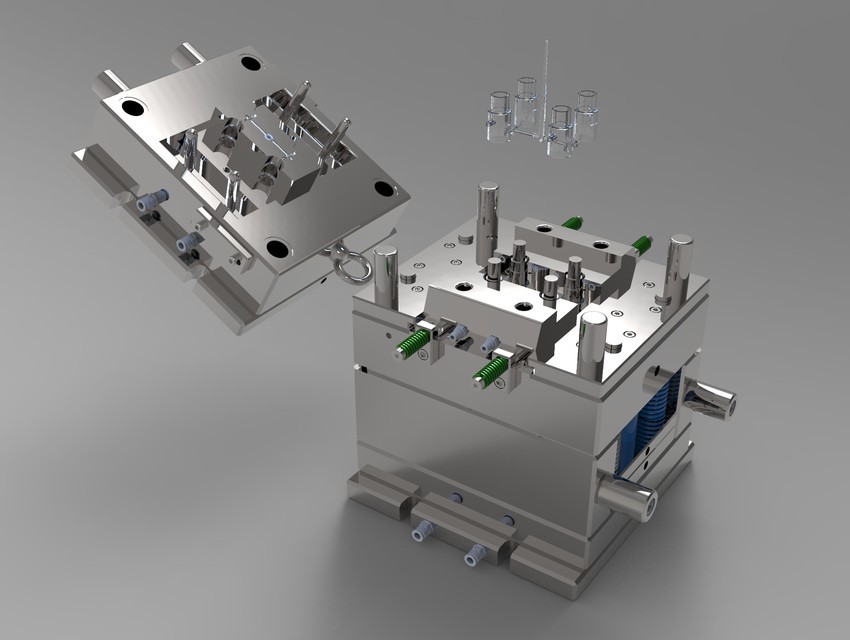
An Overview of Mold Design
Mold design involves the creation of a mold, which is essentially a hollow container used to shape materials into desired forms. The process encompasses several steps, including Machine Selection, material selection, Tool design, Process Planning and precision Manufacturing. Each of these steps must be meticulously managed to ensure the mold functions correctly, withstands the manufacturing process, and produces consistent, high-quality parts.
Machine Selection
This is one of the first key selections a Mold Designer must make based on the size of the part. The platen size and tonnage of the machine determines the size of the Mold base and auxiliaries. Cycle times and material capabilities would be a determining factor while choosing the right Molding Machine.
Material Selection
Choosing the right materials for the mold is critical to its longevity and performance. Materials must be selected based on the type of product being manufactured, the manufacturing process, and the expected production volume. Common materials used in mold making include steel, aluminum, and various alloys, each offering unique benefits and challenges. Hot runner systems could be considered to reduce material wastage and improve cycle time for high volume parts.
Tool Design
Tool design involves the detailed engineering of the mold, including the design of cavities, cores, cooling systems, and ejection mechanisms. Precision in tool design is paramount, as even minor errors can lead to defects in the final product, increased production costs, and extended lead times.
Process Planning
Tool design is often accompanied by process planning for each subcomponent of the tool that takes it from raw material to finished subcomponent of the tool. For example, the guide pins are purchased as rod and go through a lathe machine -> heat treatment -> cylindrical grinding to be fit into the tool. Process planning adds extra material for each sub process. Additionally, electrode drawings, electrode position dimensions and EDM – DXF files are provided as well.
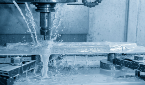
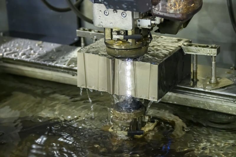
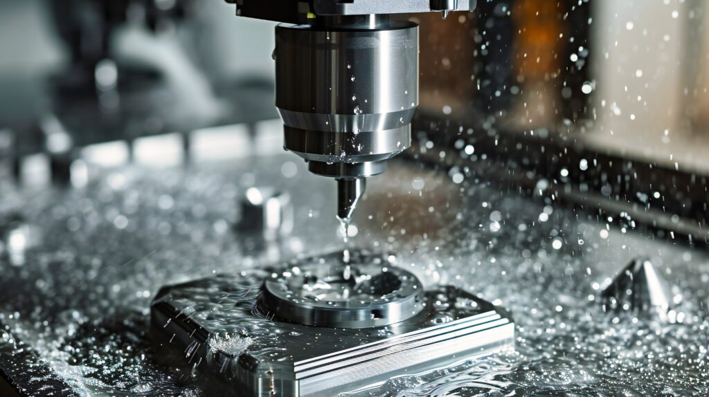
Precision Fabrication
Process planning is input for a smooth fabrication of molds. This often requires advanced machinery and skilled technicians. Precision fabrication ensures that the mold components fit together perfectly and function as intended. Technologies such as CNC machining, EDM (Electrical Discharge Machining), Wirecut EDM and additive manufacturing are commonly employed in mold fabrication. Two halves of the mold are final assembled, often employing blue matching to ensure the accuracy of the mold is consistent with design. Mold trials are conducted to trouble shoot any tolerance stackup are causing discrepancies in part production.
Manufacturing Efficiency
Cycle Time Reduction
A well-designed mold can significantly reduce the cycle time of the injection molding process. Efficient cooling channels, optimal gate design, and proper venting all contribute to faster production cycles. This, in turn, leads to higher throughput and lower production costs.
Material Efficiency
Mold design knowledge allows for the efficient use of materials. By minimizing waste and optimizing the mold cavity layout, designers can reduce material consumption. This not only cuts down on costs but also aligns with sustainable manufacturing practices by reducing the environmental footprint.
Maintenance and Longevity
Molds are substantial investments in the manufacturing industry. Proper design and maintenance considerations can extend the lifespan of molds, ensuring they remain functional and efficient over prolonged periods. This reduces downtime and the need for frequent mold replacements, further enhancing manufacturing efficiency.
Innovation and Customization
Complex Geometries
Advanced mold design knowledge enables the creation of complex geometries that would be challenging or impossible with traditional manufacturing methods. This opens up new possibilities for product innovation, allowing designers to push the boundaries of what can be achieved with plastic parts. Knowledge of parting lines, where to add radii and minimum radii possible are a few examples of Mold Design knowledge helping design engineers in choosing the right features and understand manufacturing limitations. Though there are ways to achieve complex geometries, Mold manufacturing knowledge like draft angles and undercuts can simplify product design and reduce expensive side action molds.
Customization
Mold design allows for a high degree of customization in plastic part production. Designers can tailor molds to produce parts with specific features, textures, and functionalities, catering to diverse market needs. This flexibility is invaluable in industries like healthcare, where customized components are essential. Advancements with multi material manufacturing and gas assisted molding make it possible to make lighter parts and have different finishes with different and cheaper core materials.
Cost-Effectiveness
Reduction of Defects
By incorporating robust mold design principles, manufacturers can significantly reduce the occurrence of defects. This leads to fewer rejected parts and lower rework costs, ultimately contributing to a more cost-effective production process.
Tooling Costs
Understanding mold design intricacies can help in optimizing tooling costs. By designing molds that are easy to manufacture and maintain, companies can reduce initial tooling expenses and ongoing maintenance costs. This economic benefit is crucial for maintaining competitive pricing in the market. Understanding design cycle and making choices at the start can reduce rework costs in the long run. For example choosing an insert for features that are subject to change and communicating with Mold designers can help keep a tab on modifications and related costs.
Conclusion
In conclusion, mold design knowledge is indispensable in the realm of plastic part manufacturing. It not only ensures the production of high-quality, precise, and aesthetically pleasing parts but also enhances manufacturing efficiency, fosters innovation, and contributes to cost-effectiveness. As the industry continues to evolve, the importance of mold design will only grow, underscoring the need for continuous learning and expertise in this critical area. For manufacturers aiming to excel in the competitive landscape, investing in mold design knowledge is a strategic imperative that promises substantial returns in quality, efficiency, and innovation.